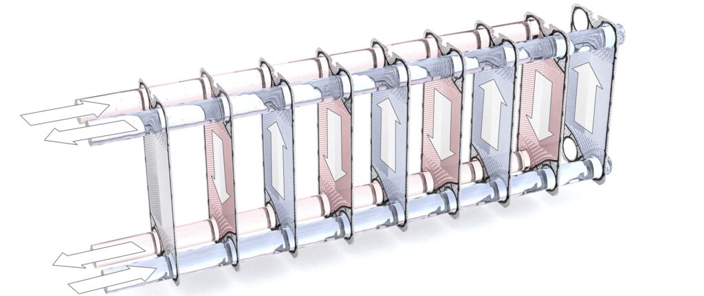
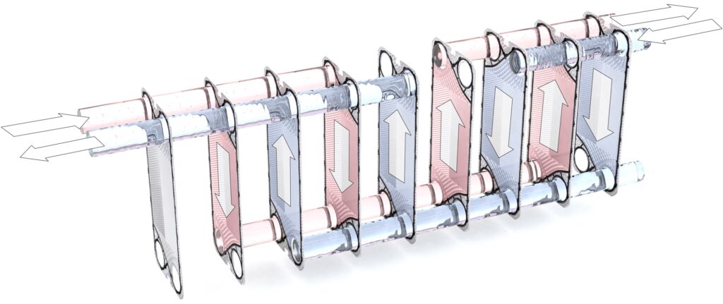
Gasketed plate heat exchangers consist of a set of adjoining embossed plates with apertures.
The plates are assembled at a 180° angle to each other, resulting in a flow gap. The gasket, which is mechanically secured or glued onto every plate, ensures that the flow gaps are securely sealed to the outside and from the second medium involved in the heat exchange.
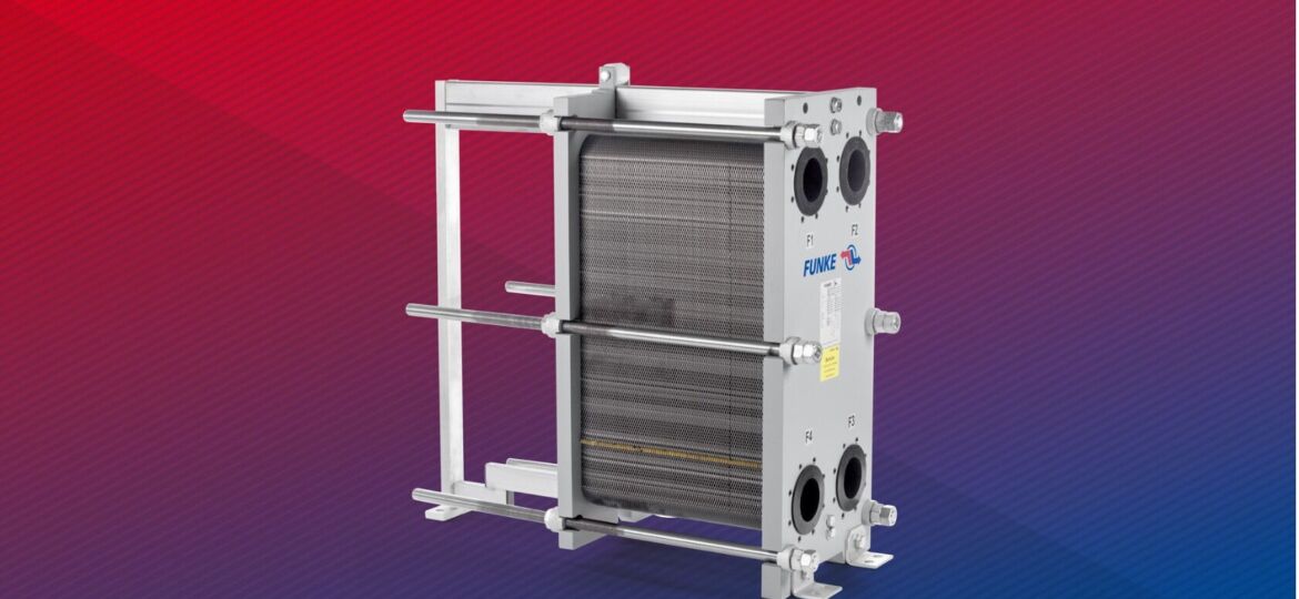
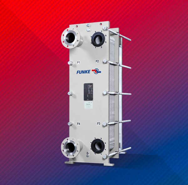
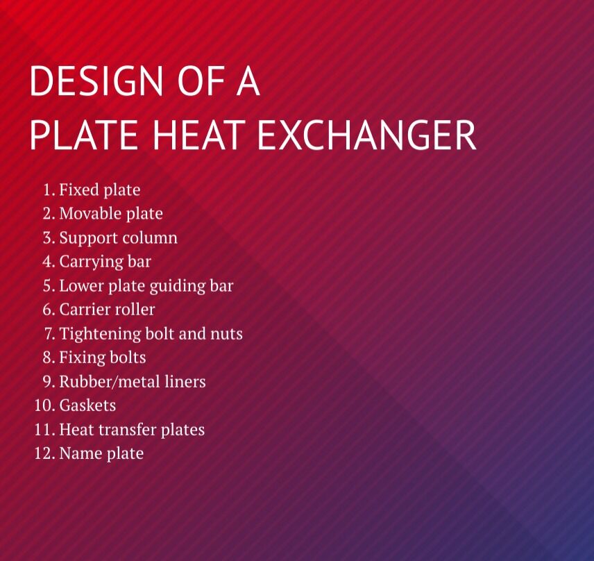
The plate assembly is mounted in a frame and compressed with tightening bolts between the fixed plate and the movable plate.
The gaskets of a plate heat exchanger experience a normal fatigue process over the course of their service life. Depending on the conditions of use, the plate assembly can be re-tightened several times until the lower limit is reached.
The connections of the media involved in the heat exchange are on the fixed plate, but can also be on the movable plate for multiple-pass flows. (see “Flow diagram”).
Our product range includes single and multiple-pass plate heat exchangers with heat exchange surfaces of up to 2,000 m².
Our plates come with a double gasket at the inlet and outlet to prevent mixing of the two media. If designed as a safety heat exchanger, double plates are provided with a special gasket system.
Special series
Safety plate heat exchangers (FPDW)
Stainless steel versions for food and pharmaceutical applications
Plate heat exchangers in redundant configuration, installed as a compact unit on base frame, incl. switch-over valve, thermostat and safety valves
COMBINATION OF PLATES AND GASKETS
FUNKE heat transfer plates are known for their thermodynamically and hydraulically optimized embossing, resulting in compact and cost-effective solutions.
Depending on the application different plate materials are being used:
1.4539 (N08904 / 904L)
1.4547 (254 SMO / S31254)
2.4066/2.4068 (Nickel 200 / Nickel 201)
2.4602 (Alloy C-22)
2.4819 (Alloy C-276)
2.4605 (Alloy 59)
3.7025 (titanium Gr. 1) / 3.7225 (TiPd, titanium Gr. 11)
Tantal
Gasket material
NBR in various qualities
EPDM in various qualities
Chloroprene
Butyl
FPM (Viton) in various qualities
etc.
Gasket attachment
Mechanically secured gaskets (standard)
Glued gaskets
YOUR BENEFITS AT A GLANCE
Plate pack
High thermal conductivity
Highly efficient self-cleaning
Unique FUNKE offset design
Optical gasket identification (color coding)
Frame
Compact design
Highly flexible (upgrade/downgrade)
Easy to service and maintain
Modular system means short production times
Tiered plate guiding bar (easier plate installation)
Connections
Rubber moldings
Metal liners
Welding neck flange
Tri-Clamp
Dairy pipe
Aseptic
POSSIBLE APPLICATIONS
HVAC
Industry
Power Plants
Chemistry/ Petro-Chemistry
Renewable Energies Technology
District heating/cooling
Hydraulics
Central cooling
Rafineries and processing (PE, PP etc.)
Geothermal plants
Thermal power stations
Automotive industry
Lubricating oil cooler
Basic chemistry Acids, alkalines etc.)
Solar power plants
Heating, ventilation, air conditioning
Process Technology (thermal plants, plastics etc.)
Generator cooling
Special chemistry (Adhesives, coatings etc.)
Water power plants
Swimming pool technology
Surface treatment
Auxiliary system cooling
Fine chemistry
Bioenergy
Supply technology
Compressor systems
Pharmaceutical industry
Wind power plants
Food industry
Fuel cell technology
DEVICE USAGES
Energy recovery
Cooling/heating products
Creating/condensing steam
Product temperature control
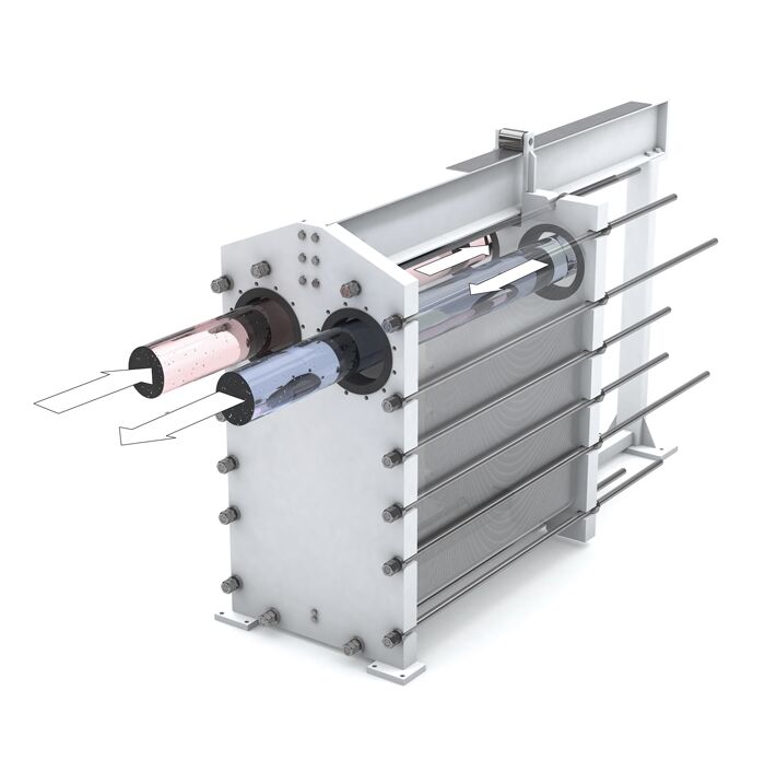
FLOW DIAGRAM/MEDIA FLOW
Plate heat exchangers can feature single or multiple-pass configurations depending on the requirements, with the single-pass configuration most commonly used.
The advantage here is that the movable plate can be removed for maintenance and servicing without having to disconnect the process connections as all the connections are located on the fixed plate.
Single-pass PHEs are most commonly used.
In single-pass PHEs, all inlet and outlet pipes are connected to the fixed plate, i.e. on the same side.
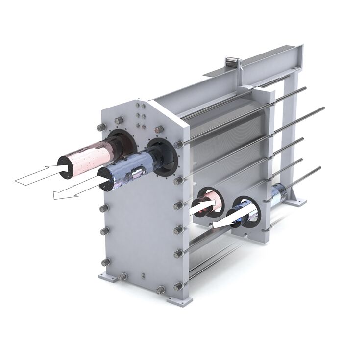
Multiple-pass PHEs may be required if there are small temperature differences between the flow media. In these systems, the connection pipes are located on both sides of the fixed and movable plate.
The media flow through the plate package multiple times according to the pass configuration.
FLOW DIAGRAm
Single-pass flow diagram all connections are located on the fixed plate
Multiple-pass flow diagram the connections are located on the hard plate and the movable plate